The Automated Garage
Description:
The Garage is a project that runs on Raspberry Pi. It has a gate that opens and closes to allow entry and exit of cars.The gate opens automatically when sensing a car. The Garage is designed and constructed based on the engineering design process that is followed in the Coder-Maker program.
Learning Objectives:
The garage is an automated system that helps students learn and apply the following:
- Coding, electronics, and physical science through a hands-on application that can be directly related to real life situations.
- Calculate period, frequency, and duty cycle based on waves
- The implementation of the engineering design process
- Application of theoretical concepts to real life situations
Materials Needed:
- Raspberry Pi with micro SD card and Raspbian
- Two ultrasonic sensors
- Micro servo motor
- Jumper wires
- Resistors 300Ω or similar
- Breadboard
- Glue gun and glue sticks
- Cutter blades or scissors
- Thin sturdy cardboard (poster or portfolio cardboard)
Setup and Functionality:
The garage is a system that is controlled by two ultrasonic sensors that are connected to a micro servo motor. The gate consists of a bar that rises up to an angle of 45° from horizontal position to open and goes back to its original position to close. The opening and closure of the bar is operated by the micro servo motor. The gate movement is fully automated. Two ultrasonic sensors are installed, one al the entrance at the level of the bar and one on the exit wall of the garage. The function of the one facing the bar is to open the bar automatically as well as preventing it from closing if a car is exiting or entering the garage and is still stopping under the bar in order to prevent damage. The function of the one on the exit wall is to give an order to the micro servo motor to open the bar automatically allowing the car to exit.
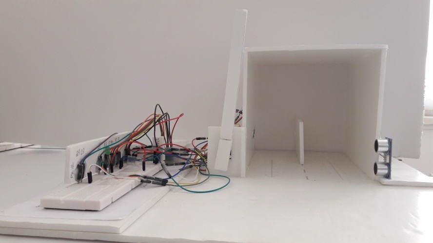
Figure 1: Shows a picture of the constructed Garage
Circuitry and Electronics:
The diagrams below show all the wiring and connections of all the componenets used in the garage:
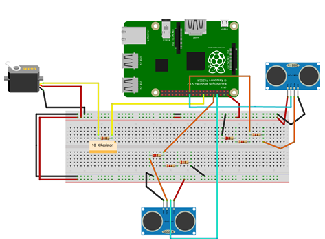
Figure 2: shows the wiring and connections of all the components of the Garage project
Warning
The micro servo motor does not consume much current and can be operated directly on the Raspberry Pi 6V power output. Make sure to use the same type of motor as other types might require a current that the Raspberry Pi cannot handle unless a transistor is added to the circuitry or an external power supply.
Programming:
The Garage is programmed using Python language:
import RPi.GPIO as GPIO
import time


trigOpen = 24
echoOpen = 23

trigClose = 8
echoClose = 10
servoM = 16

GPIO.setwarnings(False)
GPIO.setmode(GPIO.BOARD)

GPIO.setup(trigOpen, GPIO.OUT)
GPIO.setup(echoOpen, GPIO.IN)
GPIO.output(trigOpen, False)
GPIO.setup(trigClose, GPIO.OUT)
GPIO.setup(echoClose, GPIO.IN)
GPIO.output(trigClose, False)
GPIO.setup(servoM, GPIO.OUT)
servo = GPIO.PWM(servoM, 50)

distance = 7


def reading(trig, ech):
    GPIO.output(trig, False)
    time.sleep(0.3)
    GPIO.output(trig, True)
    time.sleep(0.001)
    GPIO.output(trig, False)
    signalOff = time.time()
    while GPIO.input(ech) == 0:
        signalOff = time.time()
    while GPIO.input(ech) == 1:
        signalOn = time.time()
    timePassed = signalOn - signalOff
    distance = timePassed * 17150
    distance = round(distance, 2)
    return distance

try:
    while True:
        time.sleep(0.5)
        distance = reading(trigOpen, echoOpen)
        if(distance < 5):
            isOpen = 1
            while(isOpen == 1):
                print("should open")
                servo = GPIO.PWM(servoM, 50)
                servo.start(50)
                servo.ChangeDutyCycle(12.5)
                time.sleep(5)
                distanceClose = reading(trigClose, echoClose)
                if distanceClose < 10:
                    print("can not close the gate")
                else:
                    servo.ChangeDutyCycle(7.2)
                    isOpen = 0
                time.sleep(1)
                servo.stop()


except KeyboardInterrupt:
    servo.stop()
    GPIO.cleanup()
Science Concepts and Skills:
The micro servo motor rotates 180° between start and end position. It works by action of pulse width modulation, which is an amount of repeated pulses at a set time intervals, which determine the angle and direction of rotation. The servo neutral position is considered to be at 90°, from which it can rotate 90° towards the 0° and 90° towards the 180°. A pulse of 0.5 milliseconds causes the motor to move to position 0°, 1.5 ms to position 90°, and 2.5 ms to position 180°. The motor expects to receive a pulse every 20 ms even if it does not have to make any movement. The length of the pulse will determine the direction and angle of movement.
The coding of the mini servo uses duty cycle for the rotation values. The duty cycle describes the proportion of on time to the regular interval or period of time. It can be calculated based on the frequency of the wave, the period, and the length of the pulse. The frequency of the micro servo is 50 Hertz. The period (T)=1/frequency. To find the value of the period, T=1/50=0.02 s*1000= 20 ms
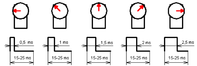
Figure 2: represents the rotation angles of the micro servo in relation to pulse duration and period.
\text{Duty cycle}=\frac{\text{length of the pulse}}{\text{period}}\times 100
For 0° position, Duty cycle=\frac{0.5}{20}\times100=2.5\%
For 90° position, Duty cycle=\frac{1.5}{20}\times100=7.5\%
For 180° position, Duty cycle=\frac{2.5}{20}\times100=12.5\%
In other words, when writing the code for the micro servo motor, 2.5 represents 0° position, 7.5 represents 90° position, and 12.5 represents 180° position. Selecting any value between 2.5 and 12.5 will lead to a corresponding rotation to an angle that is equivalent to that value.
TODO: correct figure bellow (max, min not corresponding to 45 or 135 degrees)
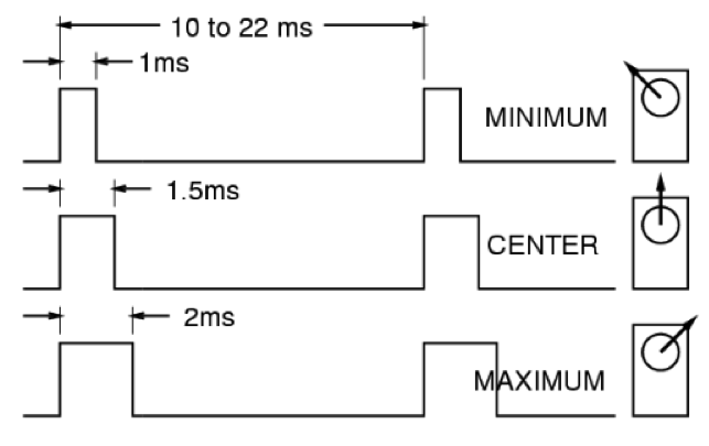
Figure 3: shows the angles of rotation of the micro servo motor as three different impulse durations, 1 ms (45°), 1.5 ms (90°), and 2 ms (135°).