7. Motors
7.1. DC Motor / Gear Motor
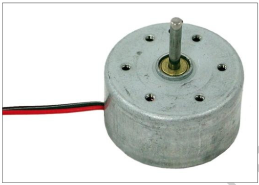
A DC motor is a type of motor that operates on a current that flows in one specific direction, like that produced by a battery. DC (direct current) motors are available in many different voltages. The 6 Volts common type usually works well on a range from 3 to 6V, which makes it a good choice for the Raspberry Pi on the 5V output or on an external power supply (battery) of 6V.
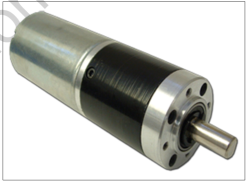
The geared motors come in various speeds that range from 10 rpm to 100 rpm (rounds per minute). They have slow rotations; however, they provide an increased torque (stronger pull) over the simple DC ones.
Connecting motors on Raspberry Pi power output alone on any GPIO pins will not work because the pi power source does not provide enough current to operate the motor. To overcome this issue, two different setups can be made. One way with boosting up the current from the Raspberry Pi power source using a transistor and the other way by using an external power supply with the use of a chip.
Simple DC Motor:
Gear Motor:
7.1.1. Using Raspberry Pi Power Source to Run the Motor
To operate the 6V DC on the RPi power source, the following materials are needed:
- RPi
- Jump wires
- Breadboard
- 6V simple DC or gear motor ! Transistor, type 2N4401
- Diode, type 1N5404
The speed and the change in speed can be controlled by the programming of the RPi-GPIO with the use of transistor.
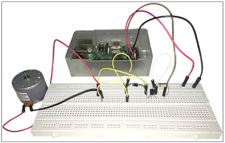
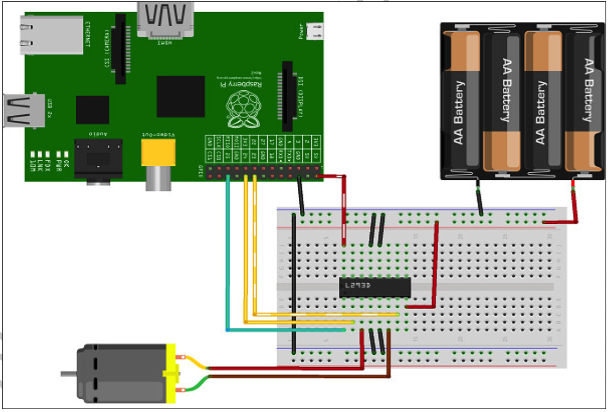
7.1.2. Controlling 2 Gear motors with Chip L293
7.1.3. Using an External 6V Power Supply
It is always an option to add an external power supply to operate devices that require relatively more current than the Raspberry Pi can provide. This will help avoiding the clashing of the Pi and protect the GPIO from any damage.
IC, L293 (or SN755410 motor drive) are required for proper functioning in case of external power source.
Warning
When working with the GPIO pins, always do this while the Pi is unplugged, as any accident by connecting (or shorting) 2 pins together can cause damage to the Raspberry Pi.
Reading pin numbers on Integrated Circuit (IC) chips is done by having the notch or dot to the left then starting from bottom left gives us pin 1.
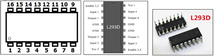
The L293 pins can be connected to the RPi GPIO’s in the following pattern:
- L293–Pin 1 to GPIO 25 (Pin 22)
- L293–Pin 2 to GPIO 24 (Pin 18)
- L293–Pin 7 to GPIO 23 (Pin 16)
- L293-Pin 16 to RPi 5V (Pin 2)
- L293-Pin 4, 5, 12 and 13 to RPi Gnd (Pin 6) and to the Gnd (negative pole) of the external breadboard.
- L293-Pin 8 to the positive pole of the external power source
The motor has two wires, one has to be connected to L293 pin 3 and the other wire to L293 pin 6.
The rotation of the motor axis, clockwise or anti-clockwise, can be easily controlled by the RPi-GPIO program with the use of L293.
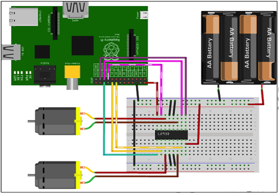
A second motor can be added to the above circuit. Adding a second motor involves just three additional wires and another motor.
L293–Pin 9 to GPIO 11 (Pin 23)
L293–Pin 10 to GPIO 9 (Pin 21)
L293–Pin 15 to GPIO 10 (Pin 19)
Motor wires, one to L293 pin#11 and the other to pin#14
7.2. Micro-Servo Motors
Micro-Servo motors are controlled by pulses of varying lengths. This gives it an advantage over the other types of motors as position and speed can be controlled by programming of the GPIO. This type of servo motors allow a rotation of only 180O, making it easy for the user to determine the position of start, stop, and the angle(s) of rotation in-between.
The Raspberry Pi has few pins that produce pulses where the servo can be connected. They are labeled on the RPi pins chart as GPIO-PWM (pulse width modulation). Other pins will work well too. The servo motor has 3 wires, one connected to the 5V RPi pin (red), the second to the Gnd (black), and a third one to the one of the GPIO pins on the RPi board.
Servo motors work on DC power supply ranging between 4.8 to 6V. However, if many are used at the same time, they might not function well on the RPi 5V output as they require a relatively higher current that might lead to crash or overload on the RPi. In this case, it is advisable to connect it to an external power source of 5 or 6V of 1 amp current as shown in the diagram below. It is also recommended to add a 1kΩ resistor on the GPIO wire to protect the Pi. In this example, we have used the GPIO pin number 12 and an external 5V power supply.
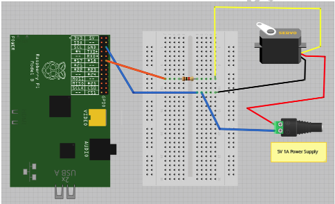
Although this will work, the PWM generated is not completely stable, so there will be a little bit of jitter with the servo.
7.3. Mini servo motor code