5. Touch sensor
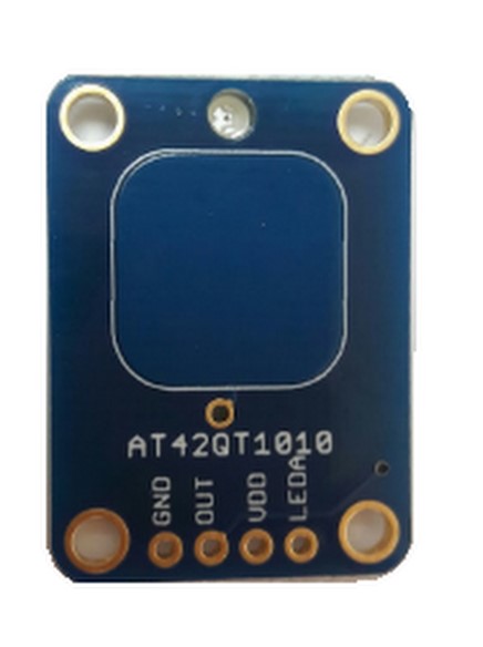
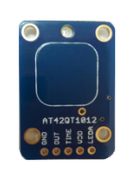
A touch sensor is a switch that toggles when touch, force or pressure is applied to it. In this tutorial we’ll be using AT42QT1012 and AT42QT1010. Both can be powered from 1.8 to 5.5 VDC, suitable with the Raspberry Pi.
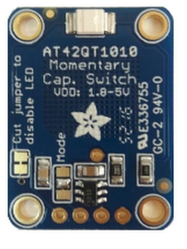
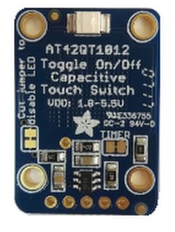
For the AT4QT1010, the switch is closed as long as a touch is detected, otherwise it’s open. As for the AT4QT1012, the switch toggles between open and closed with every detected touch. So it will stay on until it detects a touch that will turn it back off. However, an interesting feature this sensor has is that it allows setting a delay to automatically switch the output off. In this case, the pin TIME is used and connected depending on the delay that needs to be set. This is mostly helpful for saving power in case there is no way to do it manually.
5.1. Connecting the Sensor
For the sensors to work, 3 pins must be connected.
- Connect the VDD to a 3.3V or 5V pin
- Connect the GND to the ground pin.
3. OUT is the digital output that will indicate whether the switch is open or closed by giving out a HIGH or LOW signal. This can be used to control a component (LED for example) directly or through code. Connect it to any GPIO pin or as shown below and set the pin as input in order to receive the signal from the sensor.
In this example:
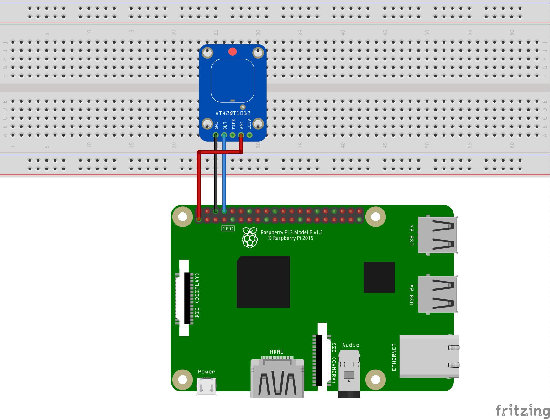
- VDD is connected to pin 1
- The GND to pin 6
- OUT to pin 8
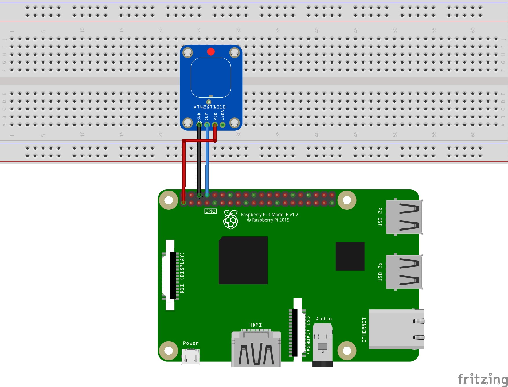
Below are the connections for each sensor.
AT42QT1012:
AT42QT1010:
5.2. Python Program to Show Switch State