1. Material
1.1. Breadboard
Breadboards are a basic building block of almost all circuits that go along with the Raspberry Pi. They are great because one can assemble and dismantle circuits on them with great ease, simply by plugging a few wires here and there without having to solder anything.
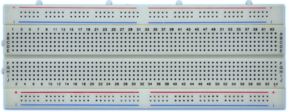
Looking at the breadboard from the front, one can observe many tiny holes with clips inside them. These clips allow you to stick a wire or the leg of a component into the exposed holes on a breadboard, which will then hold it in place. The back of a breadboard, seen below, reveals how the front is connected.
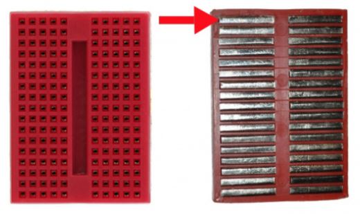
When a component is inserted in the front, it will be electrically connected to anything else placed in that row. This is because the metal rows on the back are conductive and allow current to flow from any point in that strip. Each horizontal row is separated by a crevasse that runs in the middle of the breadboard, this ensures that both sides of the row are isolated. This will come in handy later on when Integrated Chips (ICs) are to be connected on the breadboard.
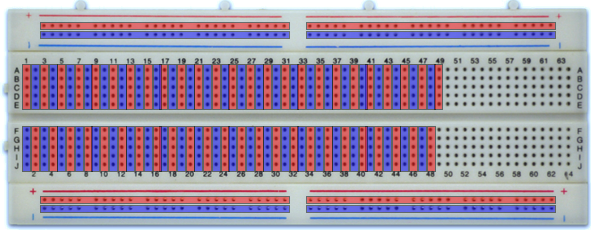
Breadboards usually have power rails that run on either side of the breadboard vertically. They are identical to the horizontal strips; however, they are usually connected all the way from top to bottom. Some breadboards may have power rails that are only connected to the middle of the board (like the breadboard shown above). These power rails give easy access to power for wherever is needed in the circuit. Typically one selects a rail for the +ve terminal of the battery and another for the -ve terminal (a.k.a. Ground).
Note
The power rails on either side are not connected, so to obtain the same power source or ground on both sides, a connection has to be established between the two sides with some jumper wires.
1.2. Jumper Cables
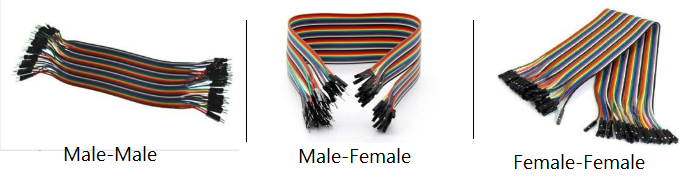
These are thin copper wires that conduct current through them from one end to another. They are the basis for almost all electronic circuits that will be assembled for the Raspberry Pi. Three types of these wires exist, each to be used according to the situation at hand. One can distinguish between the types of wires by simply looking at their ends. The ends can either be a “male” or a “female” (See below).
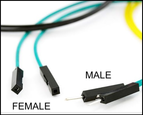
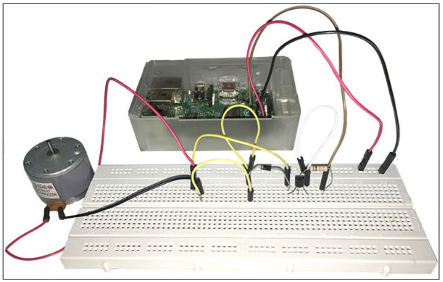
The female connection can be plugged directly into the RPi’s GPIO pins while the male connection can be plugged into the breadboard which will be discussed shortly. One can also connect a male and female together in order to extend the length of the wire if need be. You can see an example of components connected to the RPi using jumpers below:
To recap, the three types of wires are classified as follows: Male-to-Male, Male-to-Female, and Female-to-Female.
1.3. Electrical Wires
Electrical wires rolls, also available in many colors, can be used to extend the length where both ends can be made to fit in the female-type of jumper wires.