3. Active Components
3.1. Transistors
Transistors are perhaps the most important electronic components to have ever been discovered. They are behind the computer and digital revolution and are present in almost all electronic system (but are usually way too tiny to notice). For instance, the processor in your phone or your laptop is made up of billions and billions of transistors!
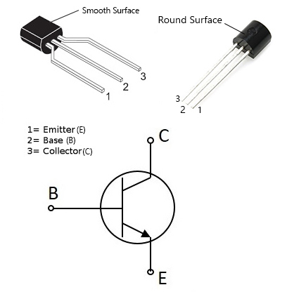
Transistors (or more specifically BJTs: Bipolar Junction Transistors) are made up of 3 pins: Base, Collector, and Emitter and can be used for many different things based on how those 3 pins are connected. A common transistor is the 2N2222 which can be seen below along with its pin information:
In this guide, we’ll mostly be connecting transistors in a way so as to switch ON or OFF a larger current than the GPIO pins can supply (i.e. a current > 16mA). To do that we will connect the transistor as shown below (in what is called a common-emitter configuration):
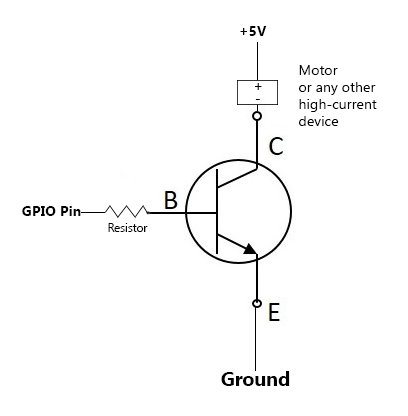
The circuit above works as follows: when the GPIO pin is on (i.e. giving 3.3V), the transistor is switched ON, and current can pass from the +5V down to the ground through the device we want to power. When the GPIO pin is OFF (0V), the transistor becomes OFF, and no current passes between the +5V and the ground at the collector.
3.2. Integrated Circuits
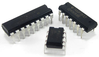
Integrated circuits, or ICs for short, are small packages that can give us a wide range of functions based on what we need. There exists ICs for many applications: analog to digital conversion, motor control, voltage comparison, signal amplification,….
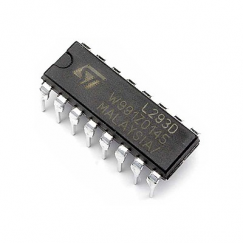
ICs can have different names, sizes, and functions. The name of the IC is usually printed on the package along with a code that gives more info about its manufacturer. Once the name of an IC is known, we can search for its ‘datasheet’ to learn more about its function and what each of its pins (metallic legs) does.
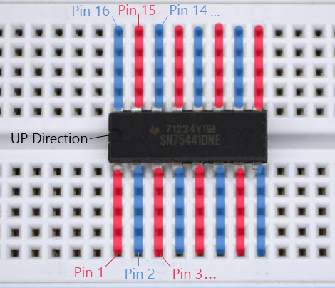
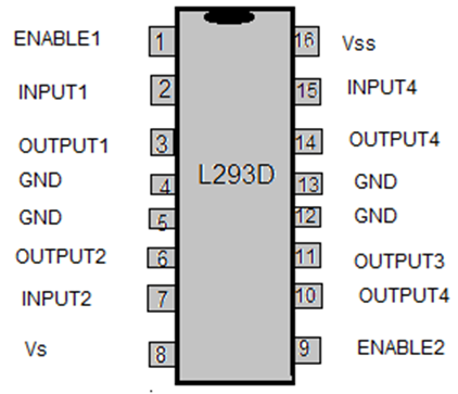
For example, you can find below an IC named L293D IC and its pin configuration (based on the datasheet):
Note
Due to the IC being a rectangle, it can be hard to tell which way is up and which way is down. Fortunately, IC manufacturers mark the UP direction with a small hole (as you can see above).
You’ll later learn what exactly the L293D is, and how it connects to the Raspberry Pi in order to control motors. But when it comes to placing it, or any other IC on the breadboard, always make sure to put it right in the middle. This way the breadboard does not end up accidentally connecting 2 opposite pins together.